| This
photo shows how to cut the notches into the top of the Azimuth Setting
circle. While the work piece is still square, you cut four
shallow
notches (about 1/8" deep).
A dado blade makes this easy since it will cut the notches the exact width you need. However, you can cut them by making multiple passes with a standard saw blade. The sides of the azimuth box will fit inside these notches and hold the base square after it is assembled. |
 |
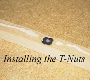
| This
photo shows one T-nut installed in the center of a small pine strip.
The white material is wood glue for attaching the strip to the edge of the azimuth box side. I also used a small air-nailer to attach the pine strip to the edge of the box side. I attached a pine the strip to both vertical and one horizontal edge of the azimuth box side. I used a total of six pine strips and eight T-nuts. |
 |
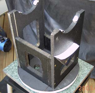
| This
photo shows how the azimuth box fits together.
You can see three of the four sides of the azimuth box. Two of the sides are the same size while the other two consist of a short and long side. You can also see two pine strips attached to the short side along the left and right edges and one pine strip along the bottom of the right side of the box. The four sides of the azimuth box are seated in the notches of the azimuth scale (which is still square at this time) and the entire assembly is being held together by the one clamp. This shows that the notch design is very stable even without any screws installed into the T-nuts. |
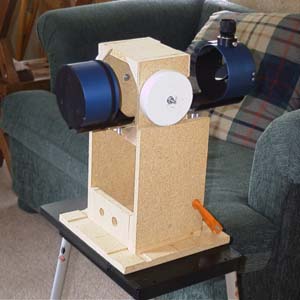 |
| This
is the completed azimuth box setting on the azimuth base.
The azimuth scale is now circular, cutouts have been made in all sides to make the assembly lighter and the circles have been cut for the elevation bearings. You can also see that small brass screws are now holding the assembly together instead of a clamp and you can see the elevation scale. |
|
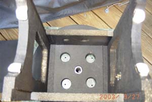
| This
shot is looking straight down into the inside of the azimuth box.
You can see the short pipe that serves as the azimuth rotational axis and four holes I drilled into the azimuth scale to lighten the assembly. You can also see the four white teflon chair tips that serve as the contact points for the elevation bearings.
|
 |
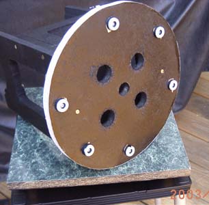
| This
is the bottom of the azimuth box showing the bottom of the azimuth
setting
circle.
I used six teflon chair tips to serve as glides for the rotation about the azimuth axis. These chair tips move
smoothly on
top of the azimuth base counter top material.
|
|
 |
|
|
|
|